Dichroic Filters
- Home
- portfolio
- Optical Filter
- Dichroic Filters
Overview of Dichroic Filters
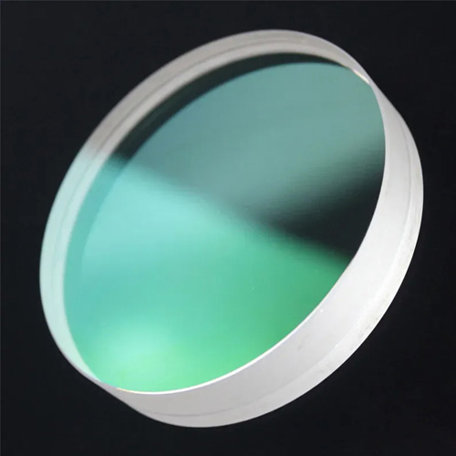
Dichroic filters are multilayer interference optical components designed to separate light into transmitted and reflected wavelength bands with high efficiency. Unlike absorption-based colored glass filters, dichroic filters utilize wavelength-selective dielectric coatings to achieve sharp spectral separation with minimal energy loss. They are essential elements in modern optical systems requiring precise wavelength routing, beam splitting, and multi-channel signal isolation.
Operating Principle
Multilayer Dielectric Interference
Dichroic filters operate based on optical interference effects generated by precisely engineered multilayer dielectric thin films deposited on optical-grade substrates. These coatings consist of alternating layers of high- and low-refractive-index materials, each with carefully controlled optical thickness on the order of a fraction of the target wavelength.
When incident light interacts with the multilayer stack, reflections from individual layer interfaces interfere constructively or destructively depending on wavelength. This interference mechanism enables selective transmission of designated spectral bands while efficiently reflecting out-of-band wavelengths. By tailoring the refractive index contrast, layer sequence, and total layer count, the spectral edge position, transition steepness, and overall transmission efficiency can be accurately controlled.
Angle of Incidence and Spectral Shift
Dichroic filters are typically designed for a specific angle of incidence (AOI), with 45° being the most common configuration in beam-splitting and fluorescence optical systems. At oblique incidence, the effective optical thickness of each thin-film layer changes, causing the spectral response to shift toward shorter wavelengths (blue shift) relative to normal incidence designs.
In addition, s- and p-polarized light experience different phase conditions at non-normal incidence, resulting in polarization-dependent spectral behavior. This divergence can affect edge position, bandwidth uniformity, and extinction performance if not properly addressed. Advanced thin-film design and optimization are therefore required to balance polarization effects, maintain sharp spectral transitions, and ensure wavelength accuracy under the specified AOI and operational conditions.
Custom Dichroic Filter Capability
Custom Spectral Design
Transition wavelength, passband width, edge steepness, blocking OD, and polarization response are precisely engineered to match defined AOI and system-level spectral requirements.
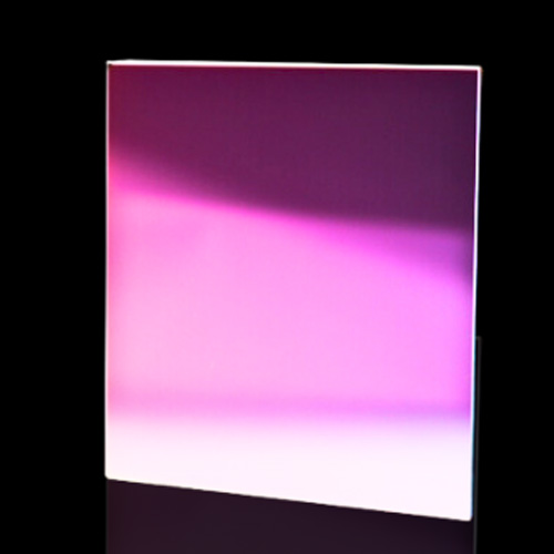
Mechanical and Optical Customization
Filter dimensions, substrate material and thickness, surface quality, and transmitted wavefront error are customized to ensure mechanical compatibility and optical stability within complex assemblies.
Prototype to Volume Production
Rapid design iteration, in-house prototyping, and scalable coating processes enable fast validation and consistent performance from initial samples to volume production.
Dichroic Longpass Filter – Example Specifications
| Cut-On Wavelength (nm) | Reflection Band (nm) | Transmission Band (nm) | Typical Size (mm) |
|---|---|---|---|
| 405 | 350 – 395 | 415 – 700 | 25.2 × 35.6 × 1.1 |
| 458 | 420 – 450 | 470 – 700 | 25.2 × 35.6 × 1.2 |
| 488 | 440 – 480 | 500 – 750 | 25.2 × 35.6 × 1.3 |
| 520 | 480 – 510 | 530 – 750 | 25.2 × 35.6 × 1.5 |
| 561 | 520 – 550 | 570 – 800 | 25.2 × 35.6 × 1.6 |
| 635 | 580 – 620 | 650 – 900 | 25.2 × 35.6 × 1.8 |
Dichroic Shortpass Filter
| Cut-Off Wavelength (nm) | Transmission Band (nm) | Reflection Band (nm) | Typical Size (mm) |
|---|---|---|---|
| 550 | 400 – 540 | 570 – 750 | 25.2 × 35.6 × 1.1 |
| 600 | 400 – 580 | 620 – 800 | 25.2 × 35.6 × 1.2 |
| 700 | 400 – 680 | 720 – 950 | 25.2 × 35.6 × 1.3 |
| 750 | 400 – 730 | 780 – 1000 | 25.2 × 35.6 × 1.4 |
| 800 | 400 – 780 | 830 – 1100 | 25.2 × 35.6 × 1.5 |
| 900 | 420 – 880 | 930 – 1200 | 25.2 × 35.6 × 1.7 |