What Are Optical Filters? Types, Principles, and Applications
Table of Contents
Introduction
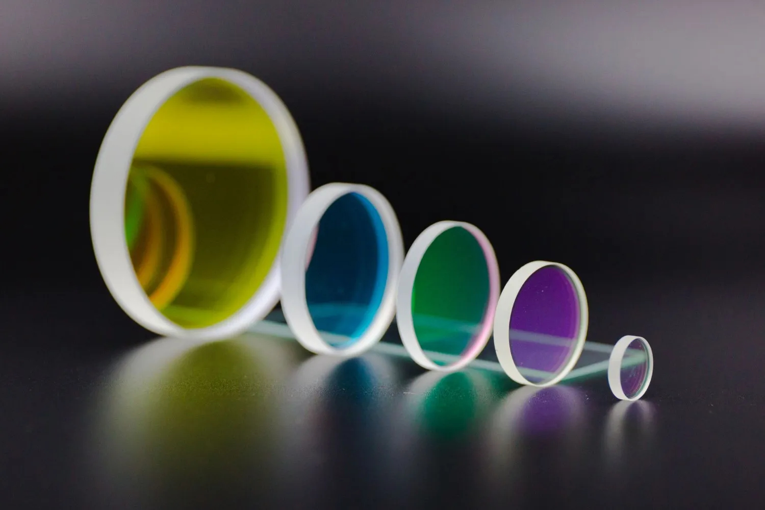
Optical filters are fundamental components in virtually every modern optical system. From smartphone cameras and medical imaging devices to laser systems and scientific instruments, filters control which wavelengths of light pass through and which are blocked. Understanding filter types, working principles, and selection criteria is essential for engineers and designers working with optical systems.
This guide provides a comprehensive overview of optical filter technology, covering the main filter categories, their operating principles, and application guidelines for proper selection.
What Are Filters in Optics?
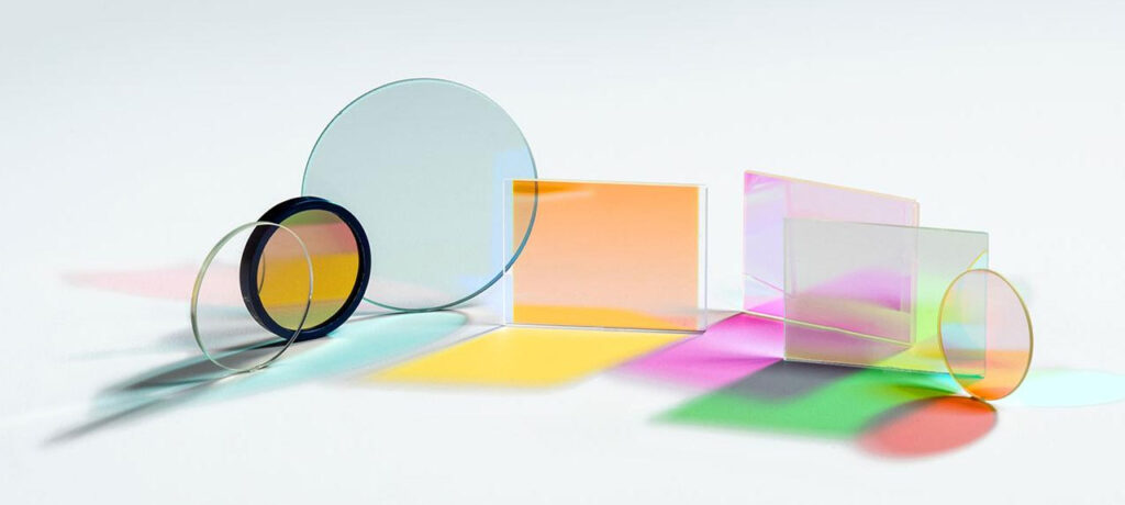
Optical filters are devices that selectively transmit light of specific wavelengths while blocking others. Unlike ordinary glass, which transmits most visible light indiscriminately, optical filters provide precise control over the spectral content, intensity, or polarization state of light passing through them.
The Role of Optical Filters
Every optical system must manage light in some way. Cameras need to block infrared radiation that would distort color images. Fluorescence microscopes must separate excitation light from emission signals. Laser systems require precise wavelength isolation. Optical filters solve these challenges by acting as wavelength-selective gates.
Basic Filter Mechanisms
Optical filters control light through three fundamental mechanisms:
Transmission: Allowing specific wavelengths to pass through the filter material. The transmitted light continues to the detector or next optical element.
Absorption: Converting unwanted wavelengths into heat within the filter material. Colored glass filters primarily work through selective absorption.
Reflection: Redirecting unwanted wavelengths away from the optical path. Thin-film interference filters and dichroic filters use reflection to achieve wavelength selectivity.
Most high-performance optical filters combine these mechanisms. A bandpass filter might use interference coatings to reflect out-of-band light while an absorbing substrate blocks any residual leakage.
Key Filter Parameters
Several specifications define optical filter performance:
| Parameter | Description |
|---|---|
| Center Wavelength (CWL) | The midpoint wavelength of the transmission band |
| Bandwidth (FWHM) | Full width at half maximum transmission |
| Peak Transmission | Maximum transmission percentage at CWL |
| Blocking | Attenuation of out-of-band wavelengths (typically expressed as optical density) |
| Cut-on/Cut-off | Wavelengths where transmission reaches 50% |
Understanding these parameters enables proper filter specification for any application.
How Do Optical Filters Work?
Optical filters achieve wavelength selectivity through two primary technologies: absorption filtering and interference filtering. Each approach offers distinct advantages depending on the application requirements.
Absorption Filtering
Absorption filters use materials that naturally absorb certain wavelengths while transmitting others. Colored glass filters contain metal ions or semiconductor particles that absorb specific spectral regions. The absorption characteristics depend on the material composition and thickness.
When light enters an absorbing filter, photons matching the absorption bands transfer their energy to the filter material, typically as heat. Photons outside these absorption bands pass through relatively unaffected.
Absorption filters offer simplicity and cost-effectiveness but have limitations. Their spectral response changes with thickness, they cannot achieve very narrow bandwidths, and absorbed energy can cause thermal issues in high-power applications.
Interference Filtering
Interference filters use thin-film coatings to achieve wavelength selectivity through constructive and destructive interference. Multiple layers of materials with alternating high and low refractive indices create conditions where specific wavelengths reinforce (transmit) while others cancel (reflect).
The coating design determines the filter’s spectral response. By precisely controlling layer thicknesses—typically quarter-wave optical thickness at the design wavelength—engineers create filters with specific center wavelengths, bandwidths, and blocking characteristics.
Interference filters enable much sharper spectral transitions and narrower bandwidths than absorption filters. They can be designed for virtually any wavelength from UV through IR, with bandwidths ranging from less than 1nm to hundreds of nanometers.
Spectral Response Characteristics
Every filter has a characteristic spectral response curve showing transmission (or reflection) versus wavelength. Key features include:
- Passband: The wavelength region of high transmission
- Stopband: The wavelength region of high blocking
- Transition region: The wavelength range between passband and stopband
- Edge steepness: How rapidly transmission changes in the transition region
High-performance optical filters achieve steep transitions, deep blocking, and high in-band transmission simultaneously—a challenging combination that requires sophisticated coating designs and precision manufacturing.
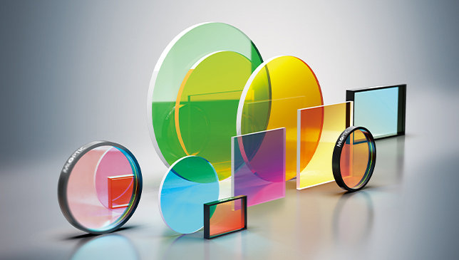
Main Types of Optical Filters
Optical filters are categorized by their spectral transmission characteristics. Each type serves specific applications and offers distinct performance trade-offs.
Bandpass Filters
Bandpass filters transmit a specific range of wavelengths while blocking both shorter and longer wavelengths outside this band. They are defined by their center wavelength (CWL) and bandwidth, typically specified as full width at half maximum (FWHM).
Narrowband vs. Wideband
Bandpass filters span a wide range of bandwidths:
| Category | Typical FWHM | Applications |
|---|---|---|
| Ultra-narrowband | <1 nm | Laser line isolation, atomic spectroscopy |
| Narrowband | 1-25 nm | Fluorescence microscopy, Raman spectroscopy |
| Wideband | 25-100+ nm | Color imaging, general illumination |
How Bandpass Filters Work
Most bandpass filters use multi-cavity interference designs. Multiple reflective stacks separated by spacer layers create resonant structures that transmit only wavelengths matching the cavity resonance. Increasing the number of cavities improves edge steepness and out-of-band blocking.
Common Applications
- Fluorescence microscopy excitation and emission filtering
- Machine vision color discrimination
- Laser line cleanup and isolation
- Spectral imaging systems
- Biomedical diagnostics
- Environmental monitoring
Longpass and Shortpass Filters
Edge filters transmit all wavelengths above (longpass) or below (shortpass) a specified cut-off wavelength. Unlike bandpass filters, they have only one transition edge.
Longpass Filters
Longpass filters block short wavelengths and transmit long wavelengths. The cut-off wavelength marks where transmission reaches 50%. These filters are essential for separating excitation light from emission in fluorescence systems and for order sorting in spectrometers.
Shortpass Filters
Shortpass filters block long wavelengths and transmit short wavelengths. They find applications in UV transmission, IR blocking, and as heat-rejection filters protecting sensitive detectors from thermal radiation.
Edge Filter Specifications
Key specifications for edge filters include:
| Parameter | Description |
|---|---|
| Cut-on/Cut-off wavelength | 50% transmission point |
| Slope | Steepness of the transition (nm from 10% to 90% transmission) |
| Blocking range | Wavelength region of high attenuation |
| Blocking level | Optical density in the blocked region |
High-performance edge filters achieve transitions of just a few nanometers while maintaining deep blocking across extended wavelength ranges.
Neutral Density (ND) Filters
Neutral density filters reduce light intensity uniformly across all wavelengths without altering spectral content. They are essential when light sources are too bright for detectors or when exposure control is needed.
Optical Density
ND filter strength is specified by optical density (OD), which relates to transmission by:
Transmission (%) = 10^(-OD) × 100
| Optical Density | Transmission | Light Reduction |
|---|---|---|
| OD 0.3 | 50% | 1 stop |
| OD 0.6 | 25% | 2 stops |
| OD 1.0 | 10% | 3.3 stops |
| OD 2.0 | 1% | 6.6 stops |
| OD 3.0 | 0.1% | 10 stops |
| OD 4.0 | 0.01% | 13.3 stops |
ND Filter Types
Absorptive ND filters use light-absorbing glass or coatings. They are cost-effective but can heat up under high-power illumination.
Reflective ND filters use metallic or dielectric coatings to reflect excess light. They handle higher power levels but may introduce interference effects.
Variable ND filters provide adjustable attenuation, useful when light levels change or precise exposure control is needed.
Applications
- Laser power attenuation for detector protection
- Photography and cinematography exposure control
- Optical testing and calibration
- Protecting sensors from damage
Notch Filters
Notch filters block a narrow band of wavelengths while transmitting wavelengths on both sides. They are the inverse of narrowband bandpass filters—rejecting rather than selecting a specific wavelength.
Working Principle
Notch filters use multi-layer interference designs optimized for reflection at the target wavelength. The blocking band is typically very narrow (a few nanometers), providing minimal impact on the surrounding spectrum.
Key Applications
Raman Spectroscopy: Notch filters block the intense laser excitation line while transmitting the weak Raman-scattered signals at nearby wavelengths. Without notch filters, the laser light would overwhelm the detector, making Raman measurement impossible.
Laser Safety: Notch filters protect optical systems and detectors from specific laser wavelengths while allowing other light to pass for imaging or measurement.
Fluorescence Microscopy: Notch filters can remove laser excitation light from emission paths when dichroic mirrors alone provide insufficient blocking.
Specifications
| Parameter | Typical Values |
|---|---|
| Center wavelength | Matched to laser line (e.g., 532nm, 785nm) |
| Blocking bandwidth | 10-40 nm |
| Blocking depth | OD 4 to OD 6+ |
| Transmission | >90% outside notch |
Dichroic Filters
Dichroic filters selectively reflect certain wavelengths while transmitting others, functioning as wavelength-dependent beam splitters. The term “dichroic” refers to this two-color behavior—the filter appears different colors in reflection versus transmission.
Operating Principle
Dichroic filters use interference coatings designed for high reflection over one wavelength range and high transmission over another. Unlike neutral beam splitters that divide all wavelengths equally, dichroic filters separate light by wavelength with minimal loss.
Key Characteristics
- High efficiency: >95% reflection and >95% transmission in respective bands
- Sharp transitions between reflection and transmission regions
- Angle sensitivity: Spectral properties shift with incidence angle
- Low absorption: Most light is either reflected or transmitted, not absorbed
Applications
Fluorescence Microscopy: Dichroic mirrors are essential components in fluorescence filter cubes, reflecting excitation light toward the sample while transmitting emission light to the detector.
Projector Systems: Dichroic filters split white light into red, green, and blue components for separate modulation in LCD and DLP projectors.
Laser Combining: Multiple laser wavelengths can be combined into a single beam using dichroic filters that reflect one wavelength while transmitting another.
Stage and Architectural Lighting: Dichroic color filters create saturated colors without absorbing light as heat, enabling brighter, cooler fixtures.
Colored Glass Filters
Colored glass filters use absorbing materials within the glass matrix to achieve wavelength selectivity. They represent the oldest filter technology and remain important for many applications.
How Colored Glass Filters Work
Metal ions, semiconductor particles, or organic dyes dispersed throughout the glass absorb specific wavelengths. The transmitted color depends on which wavelengths pass through unabsorbed. For example, didymium glass absorbs yellow wavelengths, appearing blue-purple.
Comparison with Interference Filters
| Characteristic | Colored Glass | Interference Filters |
|---|---|---|
| Edge steepness | Gradual | Sharp |
| Bandwidth control | Limited | Precise |
| Blocking depth | Moderate | Very high |
| Temperature sensitivity | Low | Moderate |
| Angle sensitivity | None | Significant |
| Cost | Lower | Higher |
| Durability | Excellent | Good (coating dependent) |
Applications
- Photography color correction
- Stage and theatrical lighting
- Landscape lighting color effects
- Flame photometry
- Educational demonstrations
- General-purpose color filtering where sharp cutoffs are not required
Colored glass filters excel in applications requiring durability, large apertures, or insensitivity to angle—characteristics that complement rather than replace interference filter technology.
IR Optical Filters
Infrared optical filters control radiation in the IR spectrum, from near-infrared (NIR, 700-1400nm) through mid-wave infrared (MWIR, 3-5μm) and long-wave infrared (LWIR, 8-14μm).
IR Cut Filters
IR cut filters block infrared radiation while transmitting visible light. They are essential in digital cameras where silicon sensors respond to NIR light that would otherwise distort color reproduction. Most camera modules include IR cut filters to ensure accurate color imaging.
IR Pass Filters
IR pass filters transmit infrared wavelengths while blocking visible light. Applications include:
- Night vision systems using NIR illumination
- Thermal imaging isolation
- IR remote sensing
- Security and surveillance cameras
Materials for IR Filters
Standard optical glass absorbs strongly beyond 2-3μm, requiring specialized materials for longer wavelengths:
| Material | Transmission Range | Applications |
|---|---|---|
| Fused silica | UV to ~2μm | NIR applications |
| Sapphire | UV to ~5μm | Harsh environment IR windows |
| Silicon | 1.2-7μm | MWIR filters and windows |
| Germanium | 2-14μm | LWIR thermal imaging |
| Zinc selenide | 0.6-20μm | CO2 laser and thermal systems |
| Calcium fluoride | 0.15-9μm | Broadband IR applications |
Each material requires appropriate coating technologies optimized for its spectral range.
Choosing the Right Optical Filter
Selecting the optimal filter for an application requires systematic consideration of optical requirements, environmental factors, and practical constraints.
Define Spectral Requirements
Begin by answering these questions:
- What wavelengths must be transmitted?
- What wavelengths must be blocked?
- How sharp must the transitions be?
- What transmission level is needed in the passband?
- What blocking level is needed in the stopband?
Consider the Light Source
The filter must be compatible with your light source:
| Light Source | Filter Considerations |
|---|---|
| Laser | Match center wavelength precisely; consider line width |
| LED | Account for spectral width; may need bandpass or edge filter |
| Broadband (halogen, arc) | Define required spectral range; blocking over extended range |
| Pulsed sources | Verify damage threshold compatibility |
| High-power | Consider thermal management; reflective vs. absorptive blocking |
Match the Detector
The filter selection should optimize signal at the detector:
- Consider detector spectral response
- Block wavelengths outside detector sensitivity if they could cause interference
- Ensure adequate signal level after filtering
- Account for filter transmission losses in system efficiency calculations
Environmental Requirements
Operating conditions affect filter selection:
| Factor | Impact |
|---|---|
| Temperature range | Interference filters shift with temperature (~0.01-0.03 nm/°C) |
| Humidity | Some coatings require protection from moisture |
| UV exposure | Can degrade certain filter types over time |
| Mechanical stress | Affects filter mounting approach |
| Cleaning requirements | Some coatings are more durable than others |
Practical Selection Guidelines
For fluorescence microscopy: Select excitation filters, emission filters, and dichroic mirrors as matched sets to ensure proper separation and minimal crosstalk.
For laser applications: Specify center wavelength precisely; consider both laser wavelength tolerance and filter manufacturing tolerance.
For imaging systems: Balance spectral selectivity against transmission efficiency; higher blocking often means lower peak transmission.
For OEM integration: Consider volume pricing, lead times, and supplier capability for custom specifications.
Summary
Optical filters are essential components that control the spectral content of light in optical systems. Understanding filter types and their characteristics enables proper selection for any application.
Key Points:
- Bandpass filters transmit specific wavelength ranges, defined by center wavelength and bandwidth
- Edge filters (longpass and shortpass) transmit above or below a cut-off wavelength
- Neutral density filters reduce intensity uniformly across all wavelengths
- Notch filters block narrow wavelength bands while transmitting surrounding wavelengths
- Dichroic filters separate wavelengths by reflecting some and transmitting others
- Colored glass filters use absorption for simple, durable wavelength selection
- IR optical filters manage infrared radiation using specialized materials
Filter selection should consider spectral requirements, light source characteristics, detector response, environmental conditions, and cost constraints. High-performance optical filters combine precise spectral control with durability and reliability for demanding applications.